
The VISNE project, from the B105 Electronic Systems Lab at the ETSIT in collaboration with the Neuro-Computing and Neuro-Robotics group at the Complutense University, focuses on the development of a thalamic prosthesis to restore vision in humans. In its initial phases, this system will be tested on rodents, specifically mice, through behavioral tests in an operant conditioning chamber, also known as a Skinner box (as can be seen in the image below) .

However, the use of animals for medical research is one of the most controversial and debated topics in the modern scientific community. Therefore, ensuring the welfare of the animals has become a fundamental task, and to this end, the aim is to remotely monitor their vital signs.
In this master’s thesis, two techniques for monitoring mice were evaluated and tested: an infrared camera (MLX90640 from Melexis) for temperature measurement and an FMCW radar (AWR6843AOP from Texas Instruments) for tracking heart rate and respiration through thoracic variations. An electronic system was designed and implemented, consisting of two components: a proof-of-concept using both sensors and a prototype PCB that integrates the temperature monitoring system.
The proof of concept was integrated with a central interface within a Skinner box for mice. A user-friendly graphical interface was developed to display measurements from both sensors over time. A program was created using the infrared camera to detect the rodent’s warm body, positioning it at the central point to enable precise tracking and presence detection. The motion data collected could be used to estimate the rodent’s stress level during behavioral tests. Additionally, this program records temperature and movement data in text files for further analysis.

System tests demonstrated that the camera enabled continuous monitoring of the mouse’s body temperature, while the radar successfully measured heart rate in humans, with results closely aligning with those obtained through traditional methods. However, the radar measurements exhibited notable variability. Additionally, the system effectively measured the respiratory cycle and accurately detected presence.

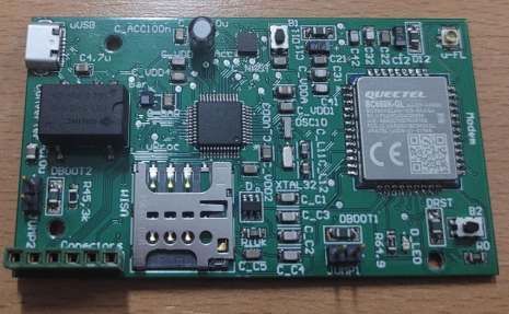
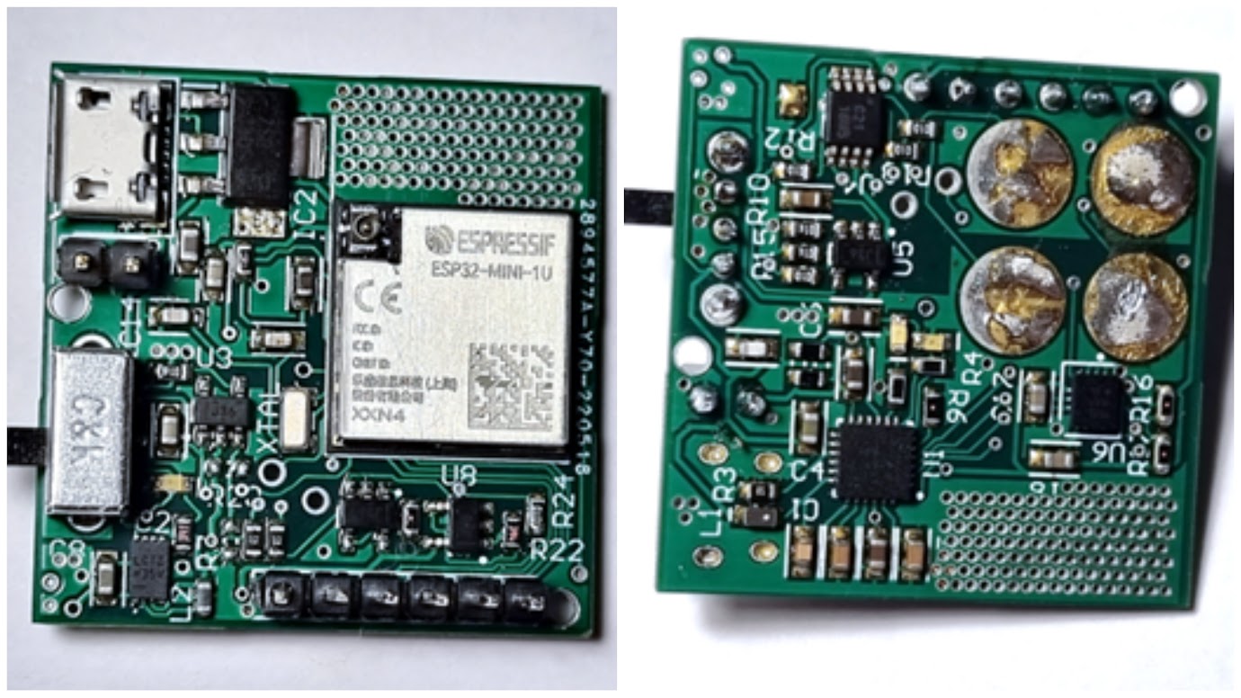
The Printed Circuit Board (PCB) for the prototype temperature monitoring system was designed and manufactured with compact dimensions of 50 x 103 mm. It includes wireless connectivity and supports data storage on a microSD card. Additionally, the PCB is equipped with a micro-USB port for easy programming and powering of the system. All the TFM’s files are available in this repository: https://bitbucket.org/b105upm/tfm_rpeon/

The PCB has been successfully soldered, tested, and programmed. The embedded software enables data communication with a central node using the MQTT protocol, while the central server capture the data and displays thermal images on a web interface. All the embedded software of this system is located in this repository: https://bitbucket.org/b105upm/skinnerbox