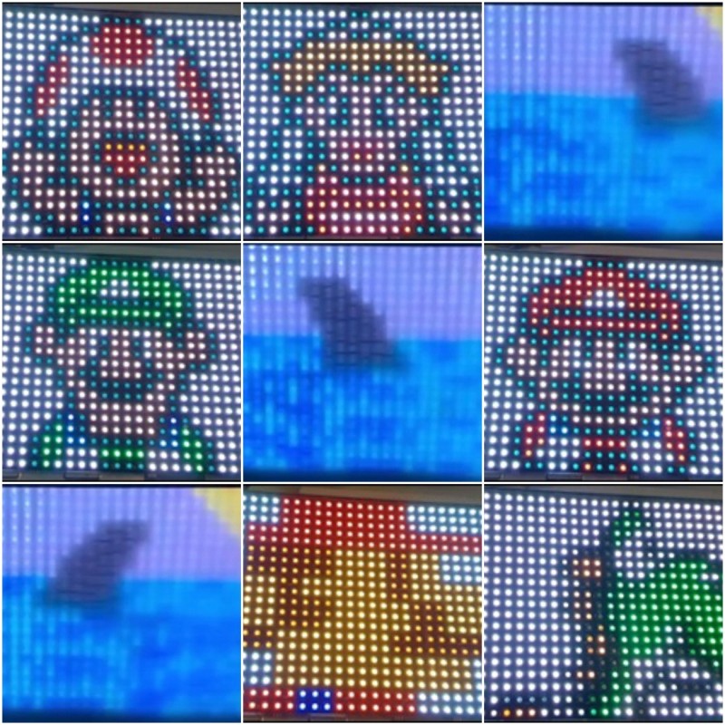
This project “A modular-reconfigurable presentation system design and implementation based on LEDs” consists of a LED screen design and development at hardware and software level, features cited in the name of this project.
In order to approach its design, we have started making an art state investigation, through which some similar projects to this one have been looked into.
Next, we carried out a hardware design and implementation. During this stage two hardware versions were developed.
Then, the software design and development have taken place. A first software stage is executed by the PC and the other stage is executed by the microcontroller. During this phase of the project we have developed many block versions which made the software architecture up.
Later, different hardware and software level tests were performed.
Finally, some full system tests were also carried out.
The project has been developed in seven phases as shown as per below chart.
As said before, the presentation system is made up of a hardware and software structure. The hardware structure is constituted by some elements, from which It is emphasized the relevant LED screen and the development board that includes a microcontroller. The software structure has been coded at PC and within a microcontroller too. This main project aim has been to desing a modular system presentation and resettting based on LEDs.
The main objective is broken down into four purposes
- Draw up a modular and reconfigurable LED screen.
- Develop a microcontroller software to allow using the LED screen.
- Develop a software by PC to display a photo on the LED screen.
- Develop a software by PC to display a video on the LED screen.
It is relevant to clarify that every pixel of this screen is encoded by 24 bits. These bits are G7, G6, G5, G4, G3, G2, G1, G0, R7, R6, R5, R4, R3, R2, R1, R0, B7, B6, B5, B4, B3, B2, B1, B0 as shown as per below chart.
The hardware architecture is a set of physical blocks through which this system is based on. In the basis of the system outcome and the hardware requirement some hardware architecture blocks have been defined. The hardware architecture that makes up the bits is described as per below.
- PC: It executes processor-transmitter software blocks.
- USB-serial converter: It Carries GRB bits forward to microcontroller.
- Microcontroller: It executes receiver-presentation software blocks.
- Logic level converter: It goes the amplitude up from the PWM to the microcontroller pins GPIO output, from 3.3 [V] to 5 [V].
- LED screen: It is made up of LED modules. Each module has 25 LEDs. For LED modules manufacturing purposes some LEDs SMD 5050 have been chosen, these LEDs mix an integrated circuit enclosed in. This circuit incorporates a signal amplifier and depending on the manufacturer also a sequential logic block. This way, the signal is empowered through each LED and 24 bits data is addressed to, from which 8 bits are related to sub LED G, 8 are linked up to sub LED R and 8 bits are connected to sub LED B. So that, color and bright are separately controlled for every LED.
- Power supply: It is setup into a star topology. Supplies 23 [A] to the system.
By means of next chart, hadware arquitecture is shown as per below.
The LED screen is composed by four module rows of LEDs, each module row is assigned by a data line as per below.
For the LEDs screen, it has been decided to use several parallel data lines, due to it aims to overcome a LEDs handicap. This handicap consists of when broadcasting a 30 [frames/s] – streaming video. It does not allow to connect more than 1024 LEDs into serial architecture. Essentially because of timing purposes. Which are exposed by means of this reasoning: If the rate to broadcast this video is 30 [frames/s], this indicates every 0.033 [s] a frame to display on LEDs is loaded. Tframe = 0.033 [s].
On the other hand, Tbit=1,25 [µs] which is a value forced by the LEDs.
As discussed earlier in this report, 24 bits are related to every single pixel, immediately after sending all bits towards the LEDs, a time must be saved for a 50 [µs] reset. This way, sending period expression, it is as it follows:
Tsend = ( 1.25 [µs/bit] x 24 [bits/pixel] x 1024 [pixels] ) + Treset = 0.03077[s]
Checking out on, Tsend < Tframe.
That is, this limitation resides in central premise that, sending time cannot be greater than frame time, whether more than 1024 LEDs are connected in cascade architecture, it is need a time greater than frame time, therefore it breaks that premise.
For the case in which the rate to broadcast this video is 60 [frames/s], could be linked into cascade connecting factors up to 512 LEDs.
Therefore, there is an inversely proportional relationship between the video rate broadcast and the number of LEDs to be connected in cascade.
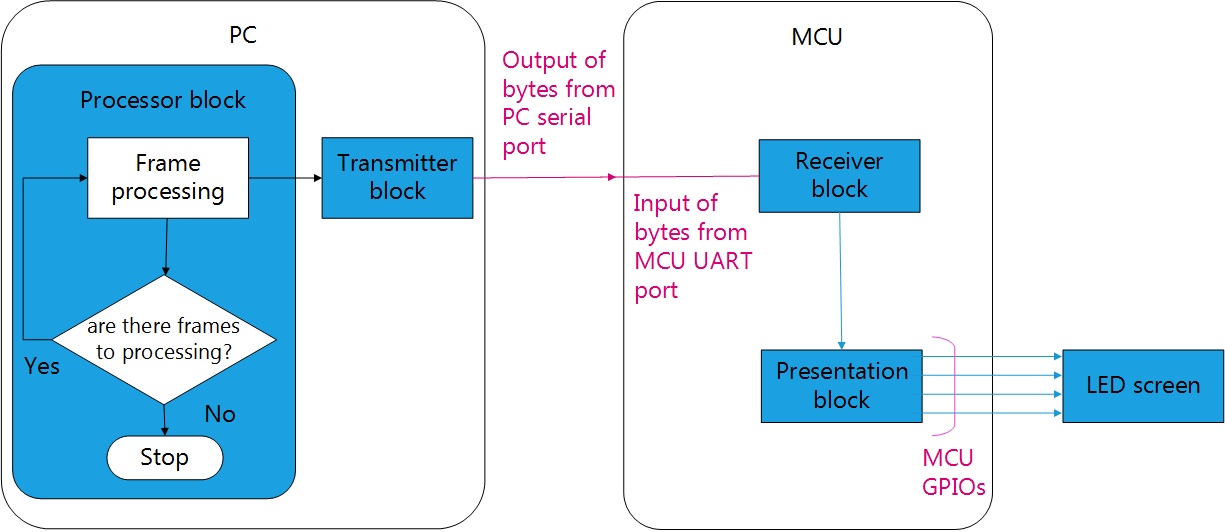
The software architecture is composed by two phases, one developed to PC and another to microcontroller.
In the PC phase, processor and transmitter blocks have been processor defined. This stage consists about reproducing a video signal and executing some processor and transmitter blocks for each frame from the video signal.
In the microcontroller phase, it is been defined both receiver and presentation blocks. In this stage continuously some bytes are received through UART and are shown on the screen.
The next diagram shows the software architecture.
Now we describe the software blocks functions
- Processor block: This block extracts the pixels from each frame and it organises them according to the data line of LED screen. Then, it moves these GRB bits to the corresponding bit of data line and then it stores those GRB bits in an array.
- Transmitter block: This block is in charge of transmitting in serial the array obtained in the processor block.
- Receiver block: This block receives in serial the bytes of array transmitted by the transmitter block. That array contains sorted pixels according to line mapping data on the LEDs screen.
- Presentation block: This block carries the symbols “1” or “0” to GPIOs MCU. Those symbols are generated as from extracted pixels from each frame. It should be clarified that GPIOD pines within microcontroller are linked up to the LEDs screen.
The symbols are illustrated below.
Consequently, it is graphically represented by the way different blocks interact one another.
For a video composed by n frames, first the processor block is run for all the pixels within frame 1, then transmitter block sends GRB bits associated to frame 1 towards MCU. After that, receiver block is run for frame 1 and while presentation block shows GRB frame 1 bits on the screen, also GRB bits are received from frame 2.
This way, successively software blocks are run for video n frames.
This system has been tested projecting a video composed by 462 frames, this video is reproduced at 29.97[frames/s] speed. Next link illustrates that test.


